Comprehensive Guide to Valve Limit Switch Boxes
Introduction to Valve Limit Switch Boxes
1.1 Definition and Primary Function
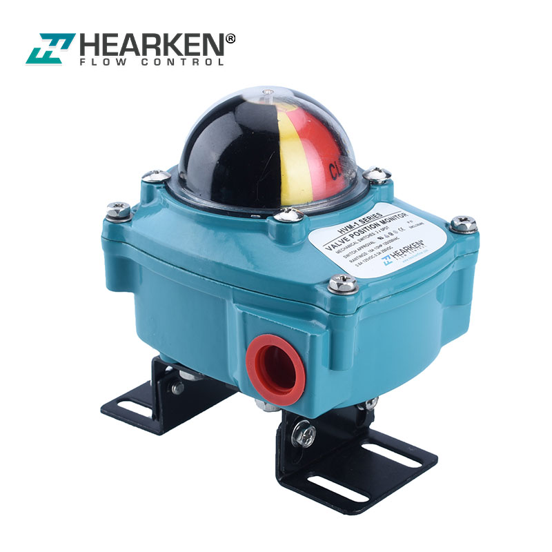
A valve limit switch box is a small electromechanical device mounted on top of a valve actuator. Its main job is to sense the physical position of the valve and send an electrical signal back to your control room. Think of it as a bridge between the physical movement of the valve and your digital computer system.
1.2 Why Feedback Matters
In a large factory, you might have hundreds of valves. If a valve fails to open, it could cause a pressure buildup or ruin a whole batch of product. The limit switch box provides "position feedback," so your PLC (Programmable Logic Controller) knows exactly what is happening in real-time.
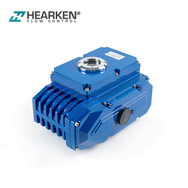
1.3 Mounting and Compatibility
Most switch boxes use a standard mounting interface called the NAMUR pattern. This makes it very easy for you to bolt the box directly onto different brands of pneumatic actuators without needing custom brackets.
A typical setup: The switch box (top) mounted to a pneumatic actuator (bottom).
Key Internal Components
To understand how it works, you need to see what's inside.
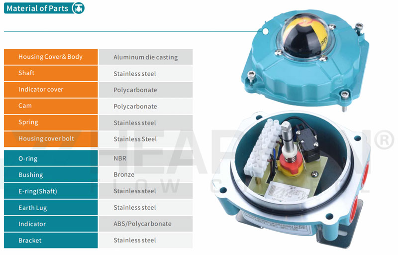
An inside look at the cams, switches, and terminal strip.
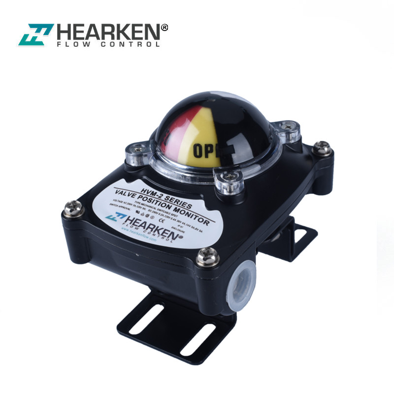
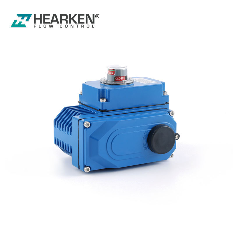
2.1 Visual Position Indicator
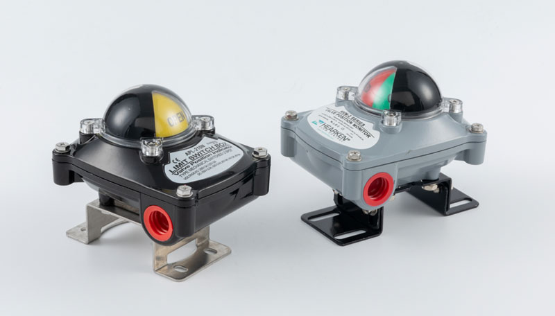
On the very top of the box, you will usually see a bright plastic "beacon." It is often colored red (for closed) and yellow or green (for open). This allows operators to clearly check the valve status from across the room at a glance.
2.2 Adjustable Cams and Striker Plates
Inside the box, there is a central shaft. Attached to this shaft are "cams" (small plastic discs). As the valve turns, these cams rotate. You can adjust them to click the switches at the exact moment the valve reaches full open or full closed.
2.3 Switch Elements (The Sensors)
These are the component that generate the electrical signal. Depending on your needs, these can be simple mechanical buttons or higher-tech magnetic sensors.
2.4 Terminal Block and Wiring
This is the hub where you connect your external field wires. It keeps your electrical connections organized and protected from the environment.
How a Limit Switch Box Works
3.1 The Mechanical Connection
The shaft of the limit switch box fits directly into the top of the valve actuator. When the actuator turns the valve, it also turns the switch box shaft at the same time.
3.2 The Triggering Process
As the shaft rotates, the pre-set cams hit the switches. This physical "click" completes an electrical circuit.
3.3 Signal Transmission
Once the switch is triggered, it sends an "On" or "Off" signal through the wires to your control system. Now, your computer knows the valve has finished its movement.
Common Types of Switches and Enclosures
The outside environment determines what type of box you need.
4.1 Mechanical Micro-switches
These are the most common type. They are cost-effective, reliable, and work just like a standard light switch. They are great for general industrial use.
4.2 Proximity (Non-contact) Sensors
These sensors use magnetic fields to detect position. Since they have no moving mechanical parts to wear out, they are perfect for valves that open and close thousands of times a day.
4.3 Enclosure Ratings (IP and NEMA)
You must choose the right housing for your environment:
- Weatherproof (IP67/NEMA 4): Use these if your valves are outside in the rain or in dusty areas.
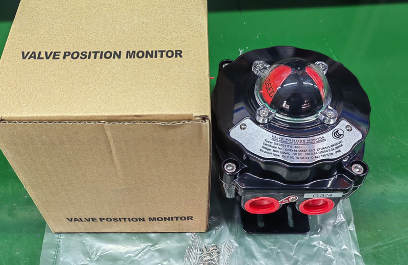
- Explosion-Proof: If you work in industries like Oil & Gas, you need these robust metal boxes. They are designed to prevent any internal sparks from causing a fire in a hazardous atmosphere.
Major Benefits and Applications
5.1 Enhanced System Safety
By using a switch box, you prevent "blind" operations. You can program your system so that a pump won't start until the limit switch confirms the necessary valve is 100% open.
5.2 Ease of Maintenance
When something goes wrong, the high-visibility indicator helps your technicians find the problem quickly. Quality brands like Hearken(https://www.hearkenflow.com/products) focus on making these boxes durable with easy-access wiring terminals, which saves you significant time during maintenance.
5.3 Industry Use Cases
- Water Treatment: Monitoring flow gates and chemical feed tanks.
- Chemical Processing: Where safety is paramount, Hearken switch boxes are often used to ensure hazardous chemicals are properly contained.
- Food & Beverage: Automating clean-in-place (CIP) systems to keep lines sanitary.
Frequently Asked Questions (FAQ)
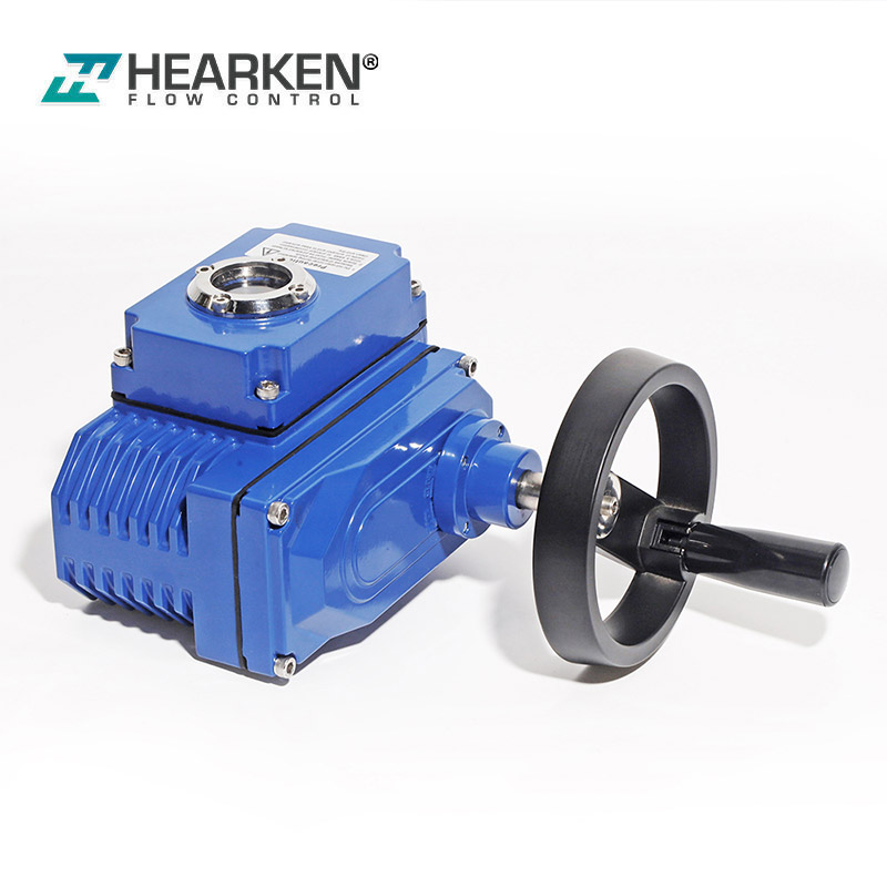
Q1. Can I install a limit switch box on a manually operated valve?
Yes, but it is less common. You will need a special mounting kit to connect the box shaft to the manual valve handle. They are primarily designed for automated actuators.
Q2. What is the practical difference between IP67 and Explosion-proof?
IP67 relates to keeping water and dust out of the box. Explosion-proof relates to keeping internal sparks inside the box so they don't ignite gases outside. You often need both ratings.
Q3. How do I adjust the "open" and "closed" positions?
You simply open the lid of the box. You can usually rotate the adjustable cams by hand (or with a small tool) until they click the switch at the desired position, then lock them in place.
Q4. Why is my control room not receiving a signal?
The most common issues are loose wiring in the terminal block, or the internal cams have slipped and are no longer hitting the switch mechanism.
Q5. Are Hearken limit switch boxes compatible with my actuator?
Likely, yes. Most Hearken models follow the international NAMUR mounting standard, meaning they fit directly onto nearly all modern rack-and-pinion pneumatic actuators.