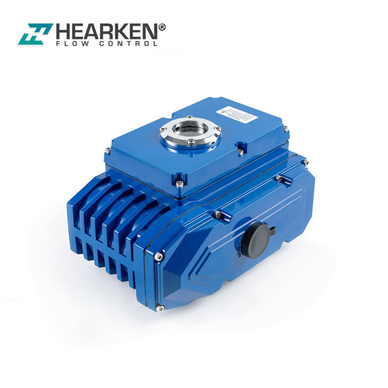
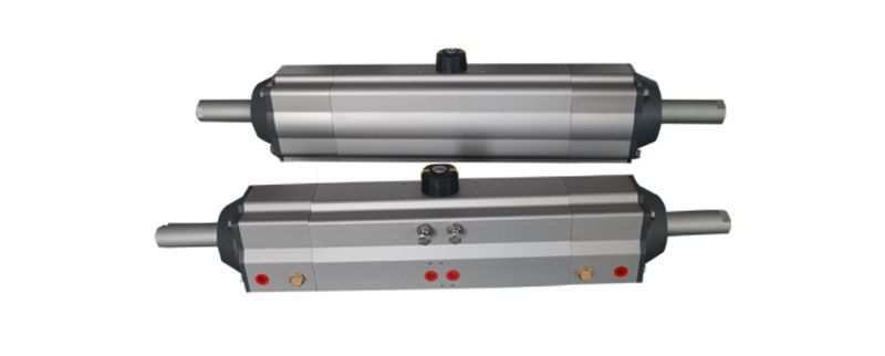
Three-position Quarter Turn Pneumatic actuators
1.Introduction
Rotary pneumatic actuator is an indispensable valve drive device in process automation control system. According to its mode of action, it is divided into double-acting (DA) type and single-acting (SR-spring return) type. Valves used to drive angular strokes, such as ball valves, butterfly valves, etc., are used in large quantities and are widely used. In many working conditions, it is often necessary for the valve to realize the intermediate position (third position) in addition to the open and closed positions.This requires a three-position rotary pneumatic actuator to achieve. However, when the working conditions also require the valve to be fully closed or fully opened in the event of a fault for safety reasons, a spring return (single-acting) three-position rotary pneumatic actuator is required to control the corresponding valve to meet the requirements of the working conditions. special requirements.
The following introduces a new type of spring return three-position rotary pneumatic actuator from the Hearken company.This new type of actuator is realized by designing a novel three-position drive structure and adjustment mechanism on the basis of the two-position single-acting actuator. This new type of actuator can realize the excellent function of convenient external adjustment whether it is fully open position, fully closed position, or intermediate position.
2.Actuator body structure
The new spring-return three-position angular-stroke pneumatic actuator adopts two pairs at both ends of the main cylinder.The serial structure of the cylinder is shown in Figure 1. The main piston in the main cylinder meshes with the output pinion.
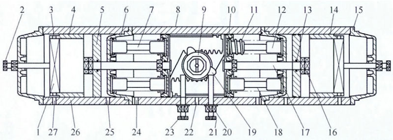
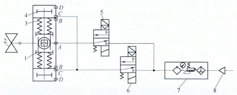
Figure 1 Spring return three-position pneumatic actuator
1.Crosspiece 2. Middle position adjusting screw 3. Ventilation hole 4. Positioning sleeve 5. Secondary piston 6. Main end cover 7. Sliding guide rod 8. Main cylinder 9. Output pinion 10. Main piston 11. Compression spring 12. Spring guide post 13. O-ring seal 14. PTFE ring 15. Auxiliary end cover 16. Limiting structure 17. Pull rod 18. Spring device 19. Limiting cam 20. Locking nut 21. Fully closed position Adjusting bolt 22. First air port 23. Fully open adjusting bolt 24. Second air port 25. Third air port 26. Auxiliary cylinder block 27. Fourth air port
When the inner cavity of the main cylinder is inhaled, the compressed air pushes the main piston, thereby driving the output pinion to rotate and driving the valve; a spring device is arranged between the main piston and the main end cover, which is a preload spring assembly. When the main cylinder loses air, the spring device pushes the main piston back to its original position, a limit cam is sleeved on the output pinion, and two limit bolts are set on the front of the outside of the main cylinder to limit the full range of the actuator. Open and fully closed. A pull rod is also installed on the main piston, and the pull rod is connected with the auxiliary piston in the auxiliary cylinder through the main end cover. An auxiliary piston is arranged in the auxiliary cylinder, and a positioning sleeve with a crosspiece at one end is arranged between the auxiliary piston and the auxiliary end cover; an adjusting bolt for adjusting the middle position is arranged on the auxiliary end cover. A first air port is arranged in the middle of the main cylinder body; a second air port is arranged between the main end cover and the main piston; a third air port is arranged on the side of the auxiliary cylinder body close to the main end cover.
3.Actuator pneumatic control principle
When the first air port on the master cylinder takes in air, the master piston moves to both ends of the master cylinder, and the master piston drives the output pinion to rotate counterclockwise and compress the spring device. At this time, the valve controlled by the pneumatic actuator opens (90° position). ); when the first air port loses air, the main piston returns to the starting position under the elastic force of the spring, the output pinion rotates clockwise and drives the valve to close (0° position), so as to meet the safety requirements of automatic valve closing in case of failure . A tie rod is fixed on the main piston, the other end of the tie rod is sealed and slidably passed through the main end cover and the auxiliary piston arranged in the auxiliary cylinder, and the end of the tie rod is provided with a limit structure, so that the first air port loses air When the third air port is inhaled, although the first air port degassing spring device pushes the valve to reset, but since the third air port has been inhaled, the auxiliary piston set in the auxiliary cylinder moves in the opposite direction of the spring return (to the pneumatic actuator). The two ends of the outer side of the auxiliary cylinder) move, and the auxiliary piston is sleeved on the tie rod, so when the auxiliary piston moves, it pulls the main piston to move outward, and when the auxiliary piston moves and touches the positioning sleeve, it stops at the required middle Location. This position is the third position or the middle position of the pneumatic actuator, and this position can be adjusted by the middle position adjusting bolt arranged on the auxiliary end cover. When the auxiliary piston stops, the end of the intermediate position adjusting bolt abuts the crosspiece on the positioning sleeve, and the other end of the positioning sleeve abuts the auxiliary piston. Therefore, by adjusting the extending length of the intermediate position adjusting bolt, the final stop position of the auxiliary piston can be easily adjusted to achieve the purpose of controlling the third position of the valve. Its pneumatic control principle is shown in Figure 2.
|
|
0 degree position |
middle position |
90 degree position |
middle position |
0 degree position |
|
solenoid valveⅠ |
OFF |
ON |
OFF |
ON |
OFF |
|
solenoid valve II |
OFF |
OFF |
ON |
OFF |
OFF |
Figure 2 Pneumatic control principle
1.Main piston 2. Valve 3. Spring assembly 4. Secondary piston 5. Solenoid valve Ⅱ 6. Air source 7. Filter pressure reducer 8. Solenoid valveⅠ
4.Epilogue
The adjustment of the middle position of the spring-return three-position pneumatic actuator is usually 20%~45% of the valve opening, that is, the opening angle is 18°~40.5°; the adjustment range of the middle position can also be expanded according to the working conditions. When it is necessary to temporarily change the intermediate position on site, the position of the auxiliary piston can be adjusted externally; it can be adjusted even during normal stable operation. In addition, in practical applications, the fully open and fully closed positions of the spring-return three-position pneumatic actuator often need to be fine-tuned on site. The new actuator can be adjusted externally.