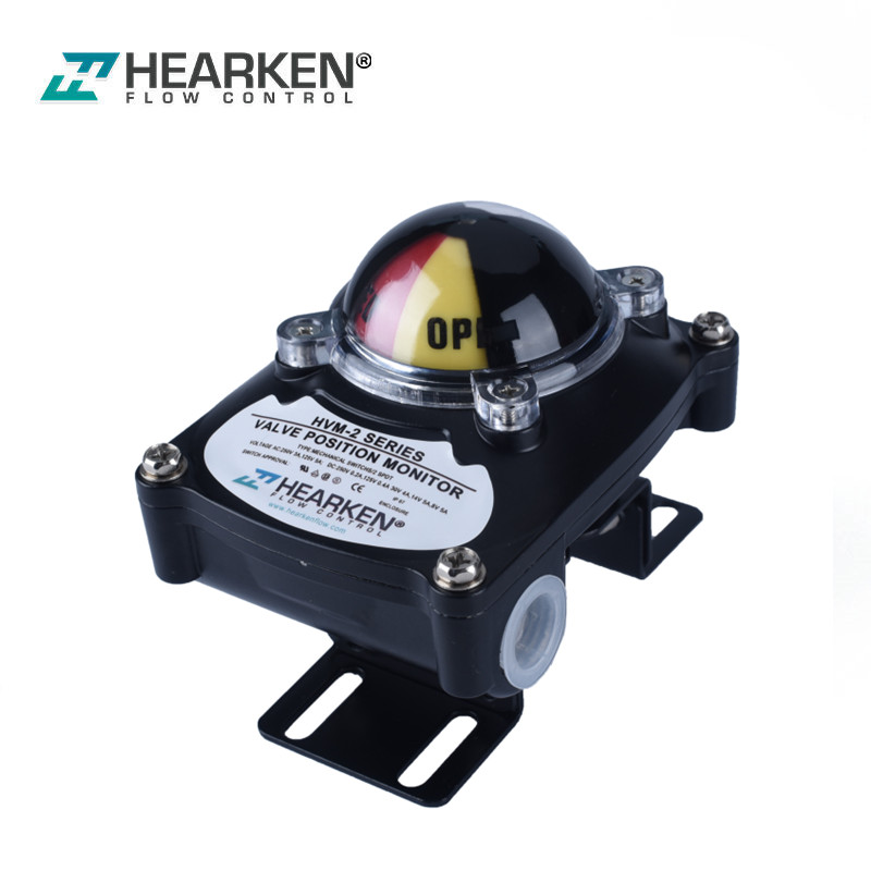
Manual Instruction of ITS300 Position Monitoring Switch
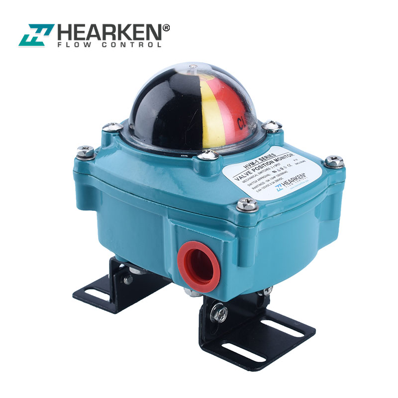
Hearken Flow ITS position monitoring switch is used for the valve and actuators which rotates 90degree quarter turn. The first function of ITS is to provide visual indication of current position of valve and actuator. Dome indicator unit shows current position by color indication. If there is full red color indication, current position of valve or actuator is fully closed position, and yellow is on fully open position. Different Color indication combination can be provided by customer’s specific requirement
Secondly Hearken Flow ITS provide electrical signal at the fully open or closed position by activating mechanical switches (SPDT and DPDT), Proximity sensors and other magnetic sensors which independently makes function. Switches vary in a wide range and construction to meet customer’s requirement.
ITS has function direction tree installation on valve different, and generally no need to adjust position of the internal cams to activate the switches as long as 0 at close and 90 at open because of adjustable cam. If it is required, customer can adjust it easily with finger or hand watching it’s movement. Red is for close position and Yellow is for open position.. Enclosure is designed to protect inside according to EN50014 and 50018, Ex d IIC T6 , and so can be used in Zone 1, 2, gas group IIB &C without any problem.
Installation
Please check the switch type and rating on the name plate on ITS enclosure, and be careful not to electrically exceed the switch rating.
All installation and maintenance should be done by authorized personnel only
Caution : In order to avoid unexpected accident, serious injury and property damage, make sure to cut all power supply to the actuator and valve before inspection, maintenance and repair , Ambient temperature : -20oC ~~+80oC
Direction and positioning of installation: No limitation excluding hazardous area
Mounting
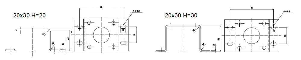
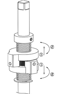
Proper size of Mounting bracket is required for mounting ITS on valve or actuator. Standard Mounting bracket is provided together with ITS, but in case of special making by customer for special application, please refer to the drawing in right hand-side. The most important thing in mounting is to align the shaft of valve (or actuator) and ITS’ shaft. ITS’s shaft is done according to NAMUR standard, so that it may suitable for various application without further modification.
Below drawings are the standard mounting bracket to be provided together with ITS300 as free of charge.
Electrical wiring
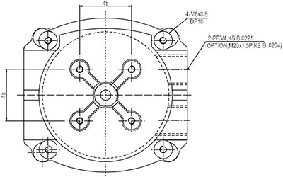
Electrical wring must be done in according to the specification of international standard or local specific regulation. ITS300 provides two PF3/4 conduit for the wiring and by using approved as explosion proof Coupling, secure the tight sealing and explosion proof function.
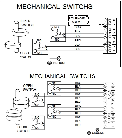
Wiring of mechanical switch
After loosing 4 screws, open upper cover. Standard ITS300 has 8 terminal strips. Strip no 1~6 are for wiring of mechanical switch or sensor contacts or for position detecting and, 7, 8 are for power for solenoid valve when required. Recommended thickness of wire is up to 15mmfor signal. By loosing screw in terminal by screw driver, and insert the wire inside of terminal strip and tight the screw again. Please refer to right hand-side wiring.
Caution: Make sure to use electricity within the rating of mechanical switch.
Wiring for proximity sensors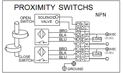
Wiring is just same with that of mechanical switches, but since operating type can be different depending on sensors type, so must follow the provided wiring method. (Right hand-side wiring is the sample of 3 wire type Proximity sensors)
Indicator setting
By operating actuator or valve, check if indicator shows correct position of actuator or valve or not. Generally indicator is set at 0O and 90o in the factory before delivery, but it would be better set the indicator after installation ITS on actuator or valve before operating.
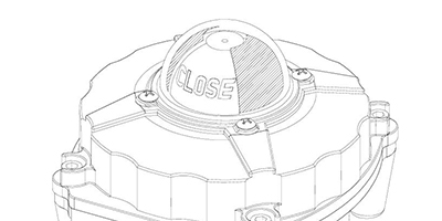
If indicator is not well aligned, loosing 4 bolts on cover, and adjus the position of transparent cover, and tight the 4 bolts again(Refer to right hand-side picture).
Setting cams and switches
Setting switch and cam can be simply done by using resistance of Multi-meter, Buzzer, or lamps.. Taking off the upper cover from lower body and putting the valve or actuator on correct position, and adjust the cam by finger checking the resistance or lamp. Locate the cam on the position which resistance is detected or lamp is on. If to set another switches, repeat above procedure. Before wiring, must cut off all power coming to the switch box.
Maintenance and repair
Regular operating of actuator or valve is required to check ITS makes function properly. make sure not to give any harmful action to other equipment or machine Checking proper work.
- Check power connecting line coming into ITS
- Check power rating(voltage, ampere or etc) is proper.
- Check Indicator shows correct position or not(refer to setting indicator)
- Check Electrical position indication is correct or not.(refer to setting switch and cam