How to Installation and Maintenance of HEA Electric Actuators?
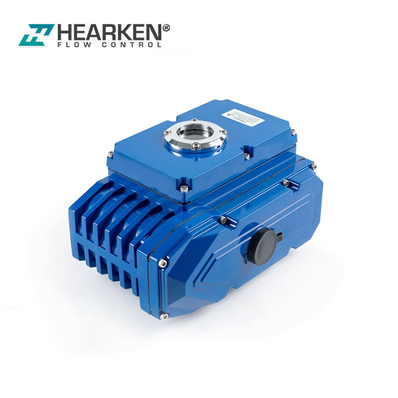
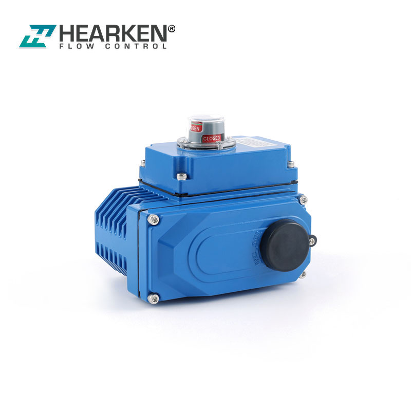
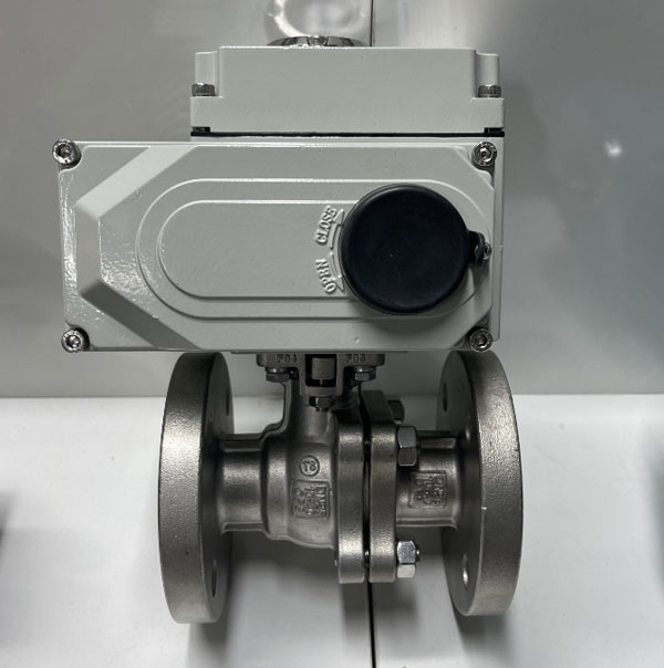
HEA series electric actuator is used for controlling 0°~270° rotation of the valves and other similar products, such as butterfly valve, ball valve, damper, flapper valve, cock valve etc. It widely applies to petroleum, chemical, water treatment, shipping, paper making, power plant, heating, light industry and other industries. Drived by 380V/220V/110V AC power or 24V/110V DC power, inputs 4-20mA or 0-10V DC control signal, moves the valve to the right position, and achieves to automatic control,the maximum output torque is 2000N·M
Installation of Electric Actuators
6.1 Installation Sites
6.1.1 Notes for interior installation
◎Pls don't install nonexplosion-proof product to the place with explosive gases
◎When installing in the submerged or outdoor, please inform us in adcance
◎Please reserve space for repairing cables, manual operation
6.1.2 Notes for outdoor installation
◎In order to avoid the rain, direct sunlight and so on, a protective cover or enclosure IP68 is avilable
◎Please reserve space for repairing cables, manual operation
6.1.3 Ambient temperature
◎Ambient temperature at '-20℃~+70℃
◎When Ambient temperature is below zero, the machine needs to install space heater
6.1.4 Fluid temperature
When equipped with valve, the heat of the fluid will move to the body, then the body temperature will rise
◎Standard bracket: when the fluid temperature is below +65 ℃, use standard bracket or no need to use bracket
◎Intermediate temperate bracket:when the fluid temperature is over -65℃, use intermediate temperate bracket
◎High-temperature bracket: when the fluid temperature is over 180℃,use high-temperature bracket.
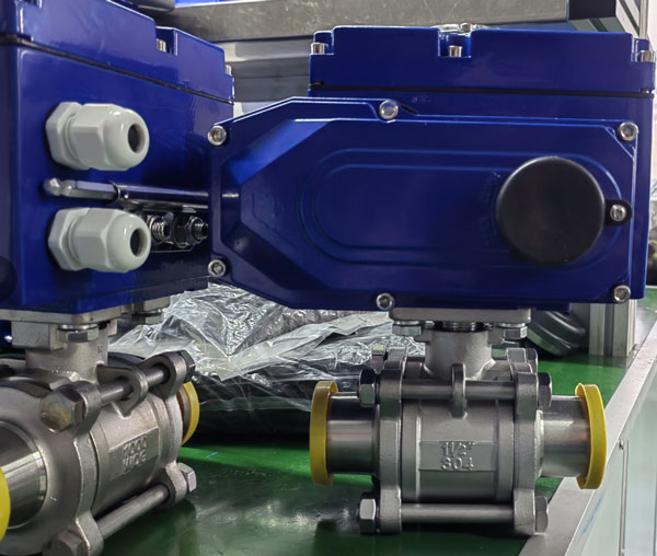
6.2 Mounting with Valve
6.2.1 Turning valve by hand, if confirmed didn't under abnormal situation,then turn to full-closed position
6.2.2 Fix the bracket on valve
6.2.3 Put the electric actuator on the bracket,then screw the bolts and nuts lightly
6.2.4 Turn the electric actuator to the closed position, fix valve mandrel and electric actuator with coupling and screw bolts
6.2.5 Fix screws on the electric actuator and the bracket
6.2.6 Rotate the electric actuator by handle to confirm non-eccentric, curved ramps, smooth movement, and pay attention not over travel!
Note: Decrease hysteresis of the coupling as far as possible.
Pay attention to keep the switch of electric actuator in line with the switch of the valve when mounting. The flange of the electricactuator bottom conform to the standard ISO5211, if the flange of valve is the same, it will be easy to debug; if don't, should to use bracket in addition.
7.Debug Description
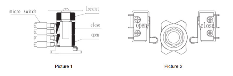
7.1 Adjustment of Stroke Limit (see picture 1,2)
Manual operate to move the electric actuator to the full-closed position. And loosen nuts on limit cam by lever, rotating limit cam ( yellow open, red close) to adjust until press down limit switch(CLS) position, and then screw limit cam nut. So, it's the way to set the full-closed stroke limit position of the electric actuator. Full-openposition setting is the same way.
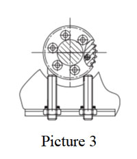
7.2 Adjustment of Mechnical Switch
Loosen the nuts of the mechanical limit, and then move the electric actuator to the full-closed position by manual, roating the limit nuts,stop until comes across inside the fan-shaped gear, and then circle out two circles, screw the nuts at last. So, it's the way to set the full-closed mechanical position of the electric actuator. Full-open position setting is the same way. Follow as the picture 3.
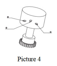
7.3 Adjustment of Potentiometer (picture 4)
Potentiometer is used for outputing feedback, with 3 pieces of terminals,meanwhile part connect with slide arm of potentiometer. When the actuator is in open moving, part connect with the end whose resistance between the slide arm decrease constantly. When the actuator is in close moving, part connect with the end whose resisrance between the slide arm decrease constantly. (Note: The potentiometer resistance should be not subzero 、 jump phenomenon.) Rotating the valve to the full-open position by lever, when the limit switch moves, measure with a multimeter to adjust the resistance between and to 35Ω~60Ω. If not correct, adjusting by rotating the drive gear of potentiometer.
8.Running Test
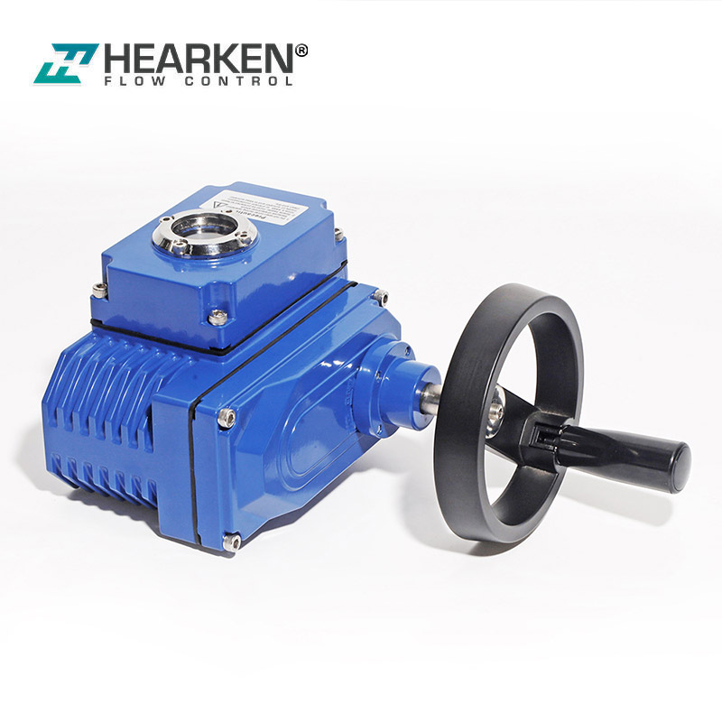
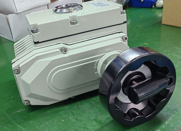
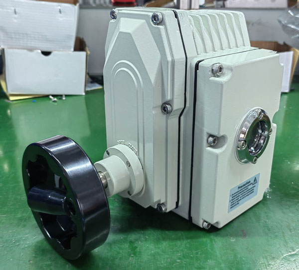
8.1 Manual Operation(picture5)
First of all, cut the power, operating by hand; take off the rubber caps on the gear cover, put the accessory lever in the hexagonal hole; rotate the lever in clockwise direction to reduce the opening.
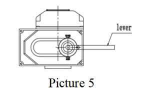
Note: Opening to the full-open or full-close position. Rotate half circle after limit switch block, if rotate excessively, it would result in the damage of other parts, so it should to avoid excessive force.
8.2 Electric Operation
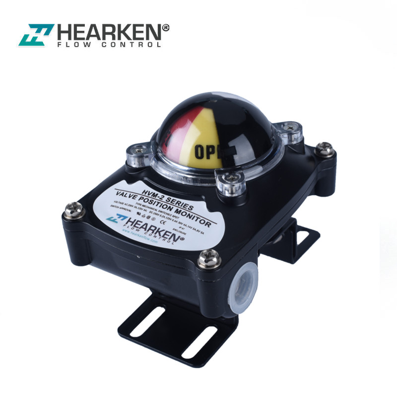
◎Checking opening meters is in line with the angle of valves by the methods of manual operation(full-open, full-closed) before electric operation;
◎Check the wiring correct, at the same time need to use an external switch to confirm opening and closing movements;
◎At lastly, start electric operation
★NOTE
1. Check wiring diagram, power supply, input/output signal correctly.
2. Don't change the internal wiring.
3. If the power supply is 3 phase, should to check the rotating direction.
Enable the electric actuator lies in a half on/ off position, turn on electricity and input the open signal.
If the electric actuator runs to the open position, which means the wiring is correct.
If the running direction is opposite, must to change 2 pieces wiring in 3 pieces of wiring.
9. Maintainence
Lubrication: Because of long life using, good pressure resistance of special Mo-based grease, so no need to refeul;
Regular operation: When the valve works infrequently, should to drive the machine regularly and checking ..