What is the Installation, Operation And Maintenance Of Limit Switch box?
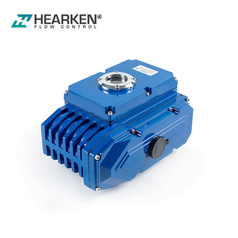
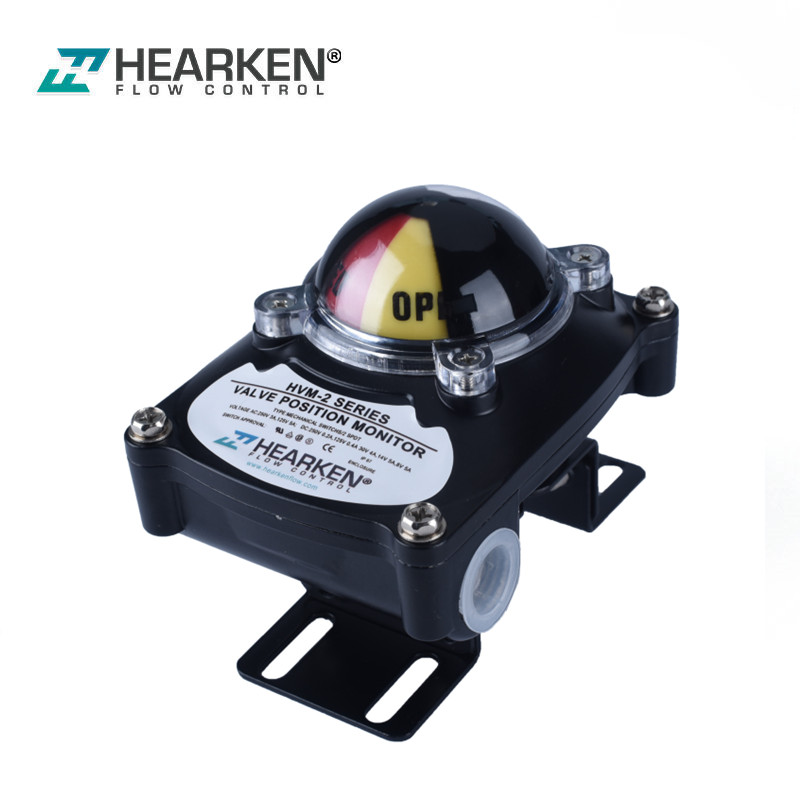
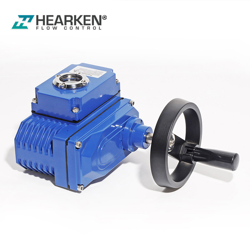
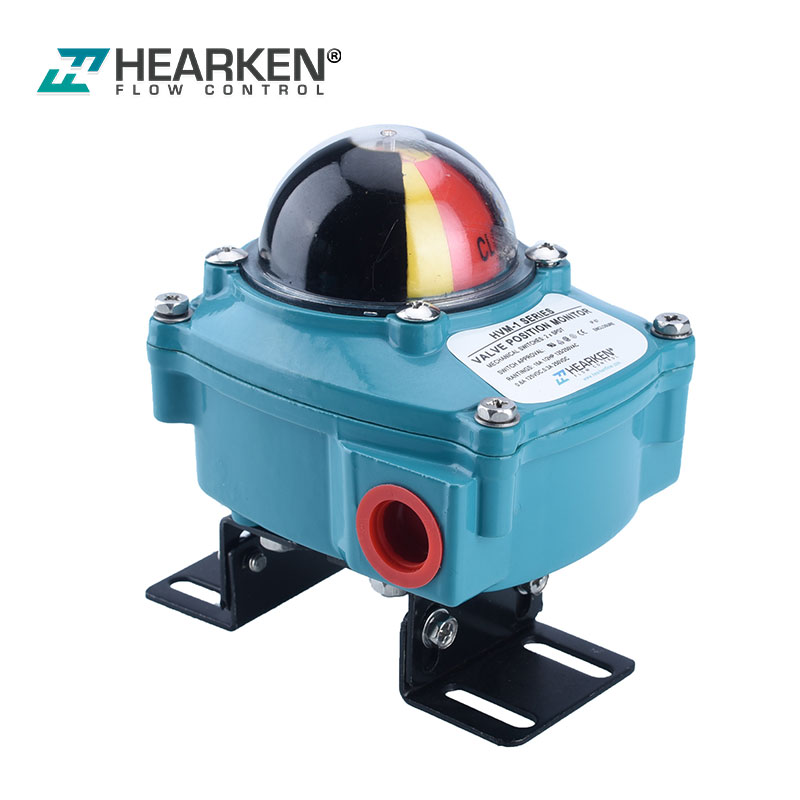
Hearken Limit Switch Box is the rotary position indication device. which designed to integrate valve and NAMUR rotary pneumatic actuator with a variety of mounting options.
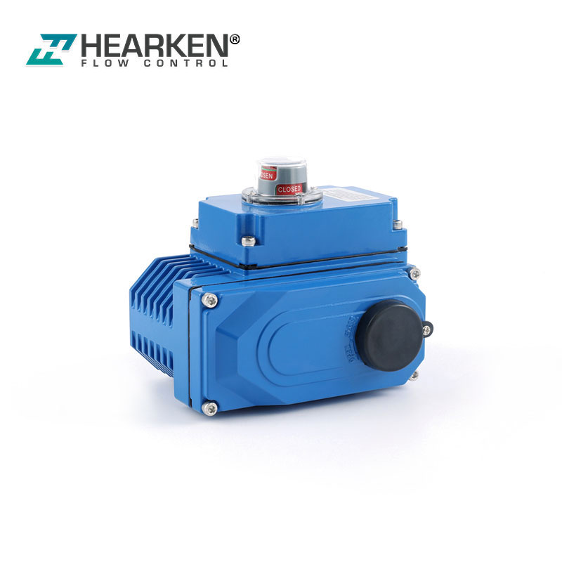
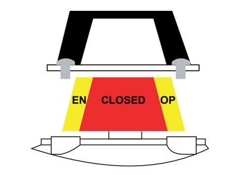
The visual indicator on the top of the device can clearly display the valve position for local detection.
Many clients will ask if the limit switch box failed, So what will be the solution and how to solve it if it’s on the application.
Please find the below tips for your to solve the problems when its failure
Limit Switch Adjustment
1. Loosen the limit switch box cover screws and remove the cover.
2. Rotate the actuator to the full counterclockwise position. This should put the valve in the fully open or closed position.
3. Lift up the bottom cam and turn until the switch clicks (this is the active position) then release the cam. Verify that the cam has been reengaged on the splined retainer. The spring will maintain the cam engagement.
4. Rotate the actuator to the full clockwise position. Then valve should now be either fully closed or open. Make note of the valve position.
5. Push down on the top cam and turn until the switch clicks (this is the active position) then release the cam. Verify that the cam has been reengaged on the splined retainer. The spring will maintain the cam engagement.
6. Align the top indicator to match to the current valve position, place the cover back on the limit switch and tighten. • Take care that the housing o-ring is properly located and the seal groove. • Keep the cover tightened down while the circuits are live. • Disconnect the supply circuits before opening
Electrical Wiring
1. Disconnect the supply circuit, then remove the top cover.
2. Remove the protection plugs from the conduit entries and install conduit or plugs suitable for the type of protection required.
3. Engage the wires in the terminal strip using a small screwdriver. • All connections are made at the number terminal strip. A wiring diagram is located inside the cover and indicates what terminal numbers correspond to the switch contacts: normally open, normally closed, common, etc. Simply follow the wiring diagram and electric code to connect the switches to your system. • Solenoids may also be wired through the switch box. At least two auxiliary terminals are include as an option. A ground screw is also included. Simply wire the solenoid to the auxiliary terminals, and then connect power leads to the opposite terminal side. • Be sure to properly ground the solenoid at the provided ground terminal
Indicator Setting
1. Remove the four screws and remove the indicator cover.
2. Lift up the indicator from the cover.
3. Set the indicator back on the cover according to valve position.
4. Replace the indicator cover and fasten with cover screws. Check to ensure that the position indicator o-ring is properly located in the seal groove. • Use only a wet cloth when cleaning the indicator. • Indicators are easily adjusted to match the dome’s clear windows or the special rotor angle indicator, such as 45°, 60° or 3 way indicator. Simply loosen the four screws to adjust the indicator. Make sure the dome window lines up with the rotor quadrants. Finally, tighten the screws to ensure a good seal.