How To Install The Linear Positioner On The Control Valve ?
Linear positioner Installation :
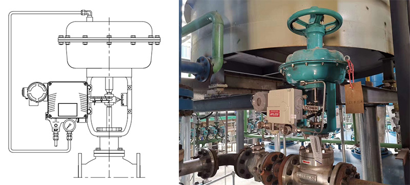
Linear positioner should be installed on linear motion valves such as globe or gate type which uses spring return type diaphragm or piston actuators..
Before proceeding with the installation, ensure following components are available. ➢ Positioner ➢ Feedback lever and lever spring ➢ M6 nut and spring washer (fastening feedback lever to a main shaft) ➢ Bracket, bolts and washers for positioner – not supplied with the positioner ➢ Connection bar – not supplied with the positioner .Preparing Bracket for the positioner Proper bracket must be made in order to adapt the positioner on the actuator yoke. Please consider following important points when a bracket is being designed. ➢ Positioner’s feedback lever must be vertical to the valve stem at 50% of the valve stroke. ➢ The connection bar of the actuator clamp for the feedback lever should be installed in such a way that the valve stroke length coincides with the corresponding figure in “mm” marked on the feedback lever. Improper setting may cause poor linearity
Installation Steps :
1) Assemble the positioner with the bracket made in previous step by fastening the bolts (M8 x 1.25P).
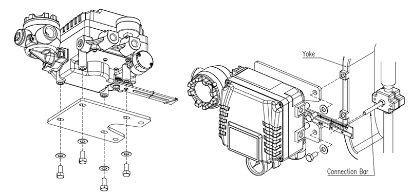
2) Attach the positioner with the bracket to the actuator yoke – DO NOT TIGHTEN THE BRACKET COMPLETELY.
3) Connect connection bar to the actuator clamp. The hole gap on the feedback lever is 6.5mm so the connection bar’s outer diameter should be less than 6mm.
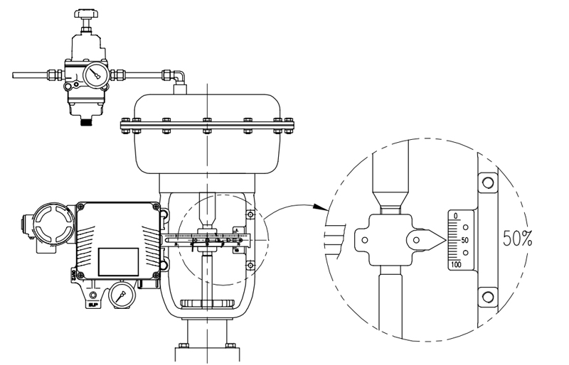
4) Connect an air-filter regulator to the actuator temporarily. Supply enough air pressure to the actuator in order to position the valve stroke at 50% of the total stroke.
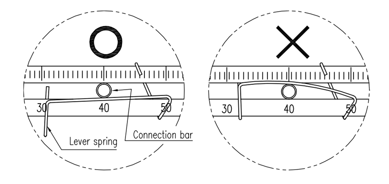
5) Insert the connection bar between the feedback lever and lever spring. The connection bar must be located upward from the lever spring as shown the below left figure. If it is located downward from the lever spring as shown the below right figure, the connection bar or the lever spring will be worn out quickly because of excessive strong tension.
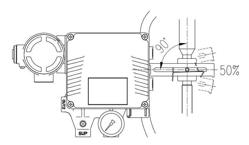
6) Check if feedback lever is vertical to the valve stem at 50% of the valve stroke. If it is not vertical, adjust the bracket or the connection bar to make vertical. Improper installation may cause poor linearity
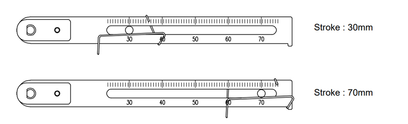
7) Check the valve stroke. The stroke numbers are engraved on the feedback lever of the positioner. Position the connection bar at the number on the feedback lever which corresponds with the desired valve stroke. To adjust, move the bracket, the connection bar or both.
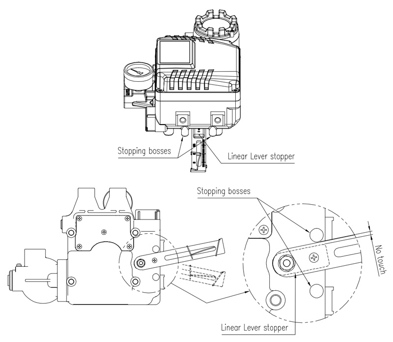
8) After installing the positioner, operate the valve from 0% to 100% stroke by using direct air to the actuator. On both 0% and 100%, the linear lever stopper should not touch the stopping bosses of positioner, which is located on the backside of the positioner. If the linear lever stopper touches the stopping bosses, the positioner should be installed further away from center of the actuator.
9) After the installation, tighten all of the bolts or nuts on the bracket and the connection bar.
Please feel free to contact with us for more information of linear positioner .