The Brief Induction on Control Valve Types
The lack of precise control over process fluids can lead to significant efficiency losses, equipment damage, and even catastrophic failures. If you fail to select and apply the correct control valve, your automation system will be operating far below its potential. This quick guide introduces the main valve types necessary to ensure the stability and safety of your operation.
Control valves are crucial devices in any industrial automation system, acting as the final control element to regulate process variables such as flow rate, pressure, temperature, and level. They function by manipulating the opening and closing of an internal plug or disc within the valve body, allowing for the precise adjustment of the amount of fluid passing through the system, thereby ensuring product quality and operational safety.
Continue reading to delve into the technical details and understand how each classification can be applied to solve your specific challenges.
Definition of Control Valve
A control valve, often referred to as the "final control element," is a mechanical device designed to intentionally modify the flow rate of a fluid medium (liquid, gas, steam, or slurry) in response to a signal from a controller. It receives an input signal (typically pneumatic or electric) and converts it into a positioning action for the valve stem. This action changes the fluid passageway area, allowing a process variable (like pressure in a tank or flow in a line) to be maintained at the desired setpoint.
The Importance of the Control Valve
The importance of control valves is unquestionable in the modern industrial landscape. They are the backbone of process control in industries such as petrochemical, pharmaceutical, power generation, and water treatment. Without them, process control would be manual and inaccurate, resulting in raw material waste, inconsistent products, high energy consumption, and risk of accidents. The performance of a control valve is often the decisive factor for the overall efficiency and safety of a plant.
Classification by Working Principle
This classification focuses on the type of process variable that the valve is designed to directly control.
Pressure Control Valve
Definition and Working Principle
Pressure control valves are used to maintain, reduce, or relieve pressure at a point in the system. They operate by opening or closing proportionally to the detected pressure. A common example is the Pressure Reducing Valve (PRV), which uses the downstream pressure to act against a spring, adjusting the internal opening to ensure that the downstream pressure remains constant, regardless of inlet pressure fluctuations.
Common Types and Application Scenarios
-
Safety/Relief Valves: Used to release excess pressure from a system or equipment, protecting it from catastrophic failure. Application: Pressure vessels and boilers.
-
Pressure Reducing Valves (PRV): Decrease the high pressure of a main line to a safer, lower operating pressure. Application: Water and gas distribution networks.
-
Back Pressure Valves: Maintain a constant minimum pressure on the upstream line. Application: Outlet of metering pumps.
Flow Control Valve
Definition and Working Principle
Flow control valves, also known as flow rate valves, are designed to modulate the rate of fluid passage. They function by varying the size of the passage opening (orifice) to create a restriction. In automatic systems, the valve receives a signal from a flow meter and a PID controller to ensure the target flow rate is maintained accurately.
Common Types and Application Scenarios
-
Needle Valves: Offer extremely fine and linear flow adjustment due to their tapered plug. Application: Instrumentation and small sample lines.
-
Globe Valves (with characterization): These are the most common as flow control valves because their internal design is ideal for modulation (throttling). Application: Precise flow control in chemical and pharmaceutical processes.
Directional Control Valve
Definition and Working Principle
Directional valves (or way valves) are responsible for guiding the flow of a fluid into different paths. They do not control the rate of flow or pressure, but rather the direction, allowing for the connection, blocking, or diversion of ports. The mechanism is typically a sliding spool or a set of seats that move to alter the connections between the inlet and outlet ports.
Common Types and Application Scenarios
-
2/2 Way Valves (Normally Closed or Open): Simply switch the flow on or off. Application: Process line blocking.
-
3/2, 4/2, 5/2 Way Valves: Primarily used in pneumatic and hydraulic systems to control the actuation of single or double-acting cylinders. Application: Machine automation, piston, and actuator control.
Classification by Drive Mode (Actuator)
The actuator is the component that moves the internal part of the valve (plug/disc) in response to the control signal.
Pneumatic Control Valve
Definition and Working Principle
The pneumatic valve uses compressed air to generate the force required to position the valve. The typical actuator is a diaphragm or piston type, where air pressure (a 3 to 15 psi signal is common) acts against a spring. This is the most prevalent type in many industries due to its simplicity, robustness, and ability to deliver high force and fast response.
Advantages and Application Scenarios
-
Advantages: Intrinsically safe (does not generate sparks), fast response speed, robustness, and low maintenance cost.
- Application: Hazardous environments (classified areas), large valves requiring high force, and processes where speed is crucial.
Electric Control Valve
Definition and Working Principle
The electric valve employs a motor (servomotor or stepper motor) or solenoid to drive the stem. In modulating systems, electric actuators provide highly precise positioning and can receive 4-20 mA signals or digital communication (HART, Fieldbus). In on/off systems, the solenoid is the simplest and fastest form of electric actuation.
Advantages and Application Scenarios
-
Advantages: High positioning accuracy, does not require compressed air (simpler for instrumentation), and easy position feedback.
-
Application: Processes requiring high accuracy (dosing), where compressed air is unavailable or expensive, and for quick-shutoff valves (solenoids).
Hydraulic Control Valve
Definition and Working Principle
Hydraulic valves use an incompressible fluid (oil) under high pressure to move the actuator. Due to the high energy density of hydraulic fluid, they are capable of generating immense forces in a compact package. The fluid is typically controlled by pilot solenoid valves that direct the oil to the main actuator, moving the valve.
Advantages and Application Scenarios
-
Advantages: Generates extremely high forces, high rigidity (low slippage or involuntary movement), ideal for large dimensions.
-
Application: Large diameter valves, high-pressure systems (like offshore oil & gas), and applications requiring massive torque.
Classification by Structural Features (Body and Plug)
This classification describes how sealing and flow control are achieved.
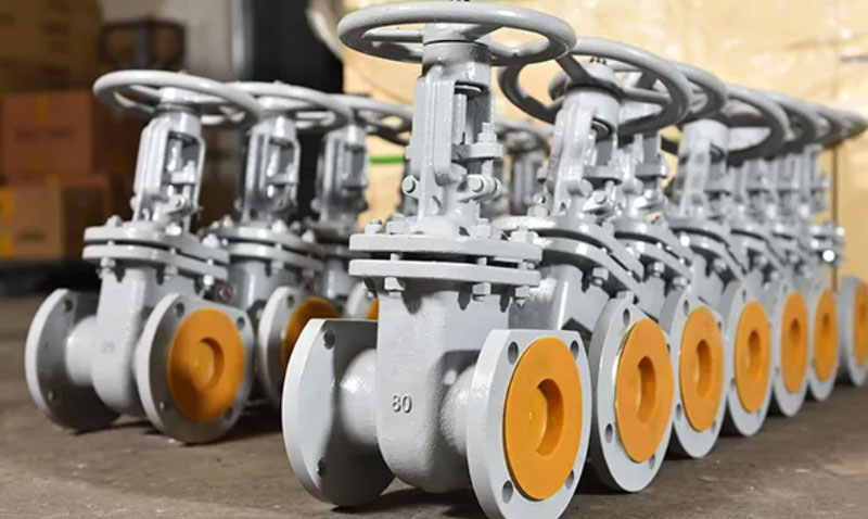
Gate Valve
Structure and Working Principle
The gate valve has a wedge-shaped or "gate" plug that moves perpendicularly to the flow, rising and lowering to allow or block passage. When fully open, the disc is removed from the flow path, resulting in minimal pressure drop.
Features and Application Scenarios
-
Features: Ideal for on/off service, low flow resistance (high flow rate), but is unsuitable for throttling (modulation) due to the risk of seat erosion.
-
Application: Fluid transport lines, where the valve must be fully open or fully closed, such as isolation valves.
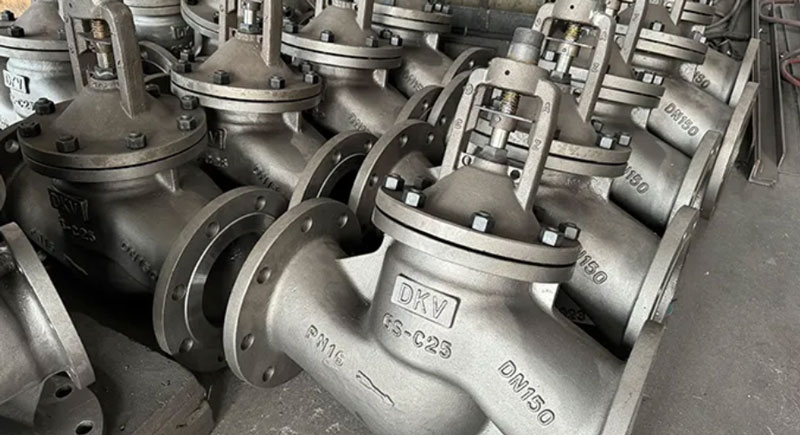
Globe Valve
Structure and Working Principle
The globe valve has a plug that moves perpendicularly to the seat, with the valve body forcing the fluid to change direction. This change of direction (which gives it a "globe" shape) creates a natural resistance that makes it excellent for throttling (modulation).
Features and Application Scenarios
-
Features: Excellent throttling and sealing capability, but it introduces a higher pressure drop than a gate valve.
-
Application: Virtually the primary choice for most flow modulation control applications.
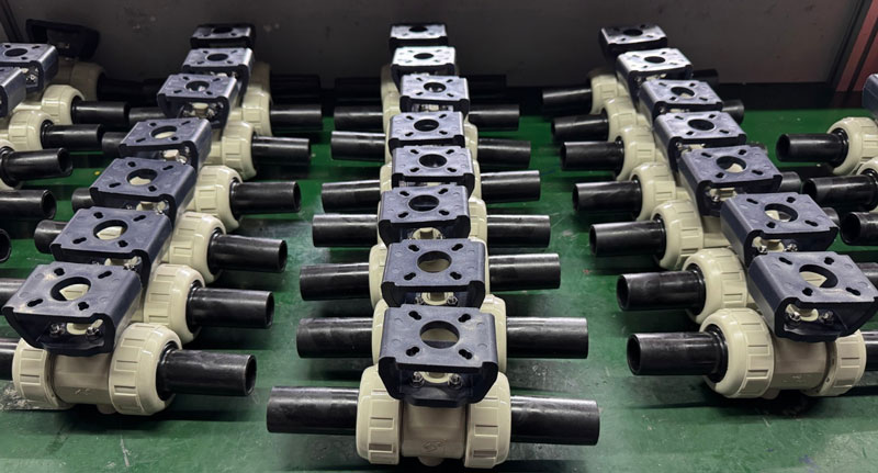
Ball Valve
Structure and Working Principle
The ball valve uses a rotating ball with a bore drilled through its center. A 90-degree (quarter-turn) rotation of the stem moves the bore from fully aligned with the flow (open) to perpendicular to the flow (closed).
Features and Application Scenarios
-
Features: Fast operation (quarter-turn), good tightness, and high flow rate when fully open. Segmented versions can be used for control (modulation).
-
Application: Fast and frequent on/off services, fluids with slurry (soft-seated versions), and line isolation.
Butterfly Valve
Structure and Working Principle
The butterfly valve has a flat disc mounted on a stem that rotates 90 degrees inside the body. The disc is always, to some extent, exposed to the flow, even when fully open, which creates some pressure drop.
Features and Application Scenarios
-
Features: Lightweight, compact, and low-cost, ideal for large diameters. It offers good modulation capability for less critical services.
-
Application: Large diameter systems, utilities (air, water), and gas and ventilation flow control.

Summary
Mastering the classifications of control valves (by principle, actuator, and structure) is essential for optimizing any process.
FAQ
1. What is the main difference between a Gate Valve and a Globe Valve?
A: The Gate Valve is ideal for on/off service and has a low-pressure drop. The Globe Valve is ideal for throttling (modulation) and has a higher pressure drop.
2. Why are Pneumatic Valves preferred in hazardous environments?
A: Pneumatic valves use compressed air for actuation and do not require electricity at the actuator, which makes them intrinsically safe because they do not generate sparks, making them ideal for classified areas (explosion risk).
3. What is the trim of a Control Valve?
A: The trim is the set of internal parts of the valve that control the flow (plug, seat, and cage). The geometry of the trim defines the flow characteristic of the valve (e.g., linear, equal percentage, or quick opening).
4. What does a 4-20 mA Control Valve mean?
A: It means the valve's actuator (or positioner) receives a standard industrial electrical control signal. 4 mA corresponds to the zero position (usually fully closed), and 20 mA corresponds to the maximum position (fully open).
5. What is the main challenge of the Butterfly Valve in modulation?
A: The Butterfly Valve's disc, even when open, creates some obstruction, and at small angles, flow control is not very accurate, limiting it to less critical modulating services.